A lot of excitement and a few days later I received the package.
So last night when I arrived home I had a spool of PLA filament with a center of electronics.
Prep and Issues
First thing I noticed was one of the Stepstick pins was a little bent so I carefully corrected that.
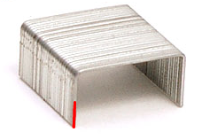
Second was the scary size of the 0805 resistors, I was expecting small, but they are tiny. I envisioned them being slightly smaller then a grain of rice which was way off the mark. The best example I can give (pictures don't really show the size too well) is pick up a standard staple then cut one of the small sections in half thats roughly the size of the smd 0805 parts.
The last thing I noticed and what took the longest to rectify was lack of markings on the resistor packaging.
With the hardware Thingfarm had labelled each bag and the items which weren't labelled were so different anyone would notice the difference.
RepRapWorld on the other hand only separated the main components of the full kit; Arduino MEGA 1280, Stepsticks, Stepstick heatsinks and the diy RAMPS board/parts.
As the resistors weren't marked up I had to read the numbering from the top. Remember how small the resistor is (as described above), now imagine trying to read a set of 4 digits from them.
I couldn't find my magnifiying glass anywhere was after a lot of rumaging and fumbling I found a pair of 1.5x magnification reading glasses.
Luckily the only resistors which could be confused are the 3x 10 with 3x 1.8k and the 5x 4.7k with 5x 10k.
I used this resistor calculator to work out the ratings (last time I resistor values where back in school years ago).
The soldering
Tools used
I had these lying around
Soldering iron
Solder
I brought these for this project
Flux pen
Soldering braid
Tweezers
With my freshly marked up resistors and clean working desk I began the fiddly process of soldering the smd parts.
I used the official RAMPS 1.4 guide from the wiki (link).
I fluxed each contact on the pcb just before soldering and used this guide for my soldering methodology (the actual soldering starts around the 7 minutes mark).
C2 was a little hit and miss, but that was to be expected as it was my first go at real smd soldering.
LED1 (the green one) threw up another curb ball, Place these with the end having green dots away from the + mark on the PCB, fine, but my pcb didn't have any + marks on it. Luckily the images on the wiki show the + mark and it was fairly easy to work out which way was which.
For some reason the red LED's (LED2, LED3 and LED4) seem to have half the width of the green LED which made soldering them a little more tricky.
R13, R14, R15, R12 and R23 all went in fine. I'd recommend soldering R13 after R12 as R12 is situated between R13 and LED1 making it a little fiddly.
Now I bet your wondering why I stopped at R23 and didn't do R24 and R25 at the same time.
Well the answer is I had a slight accident. During the soldering of R12 to R15 I managed to touch a hot section of the soldering iron with one of my fingers. I wasn't a big deal and it barely tingled, however for some reason while grabbing R24 my hand trembled, causing the resistor to shoot off the desk.
I kept my calm and soldered R25 (as I didn't want to lose that as well), then spent about 20 minutes on my hands and knees looking for it.
I was just about to give up then noticed it had landed on the top of my pc and not the floor itself.
I soldered R24 in then called it a night.
 |
| My poor burnt finger |
Time to order a loupe and clean my soldering iron (the tip isn't heating correctly).
I'll continue the soldering tonight.

No comments:
Post a Comment